|
SPI Interface
|
SPI
Interface - SPI (3v3 level)
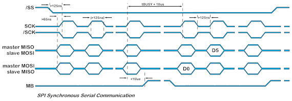
With synchronous communications enabled, data can be clocked into the TFT module
using the rising or falling edge of SCK. This is selectable by the setup command which
also sets other parameters. By default, data is clocked in on the rising edge with
the most significant bit sent first. The /SS pin can be used as an enable pin if other devices are connected to the serial line
and also allows byte synchronization. If MB is set high, the input buffer is
full or disabled.
A dummy/end byte for reading and buffer status can be set by the user.
LINK the SPI jumpers on the back of the 4.3, 5.7 and 7.0 inch modules.
SPI Master - solder pads 1&2, 3&4, 5&6 on J11
SPI Slave - Solder pads 1&2, 3&4, 5&6, 7&8 on J11
In slave mode the /SS input must be pulled
LOW if master device has no /SS output.
In slave mode the /IRQ pin is driven LOW to signify data is present in the
transmit buffer.
Although the clock is capable of 90MHz, the practical speed is probably a
maximum of 1MHz for external SPI communication.
Please test your implementation extensively.
|
.jpg)
Single Slave
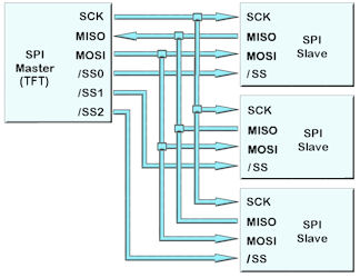
Multiple Slave |
 |
|
spi - set up parameters |
|
setup(spi)
{
set="SHRC";
//quick set up as (M)aster/(S)lave, idle (L)ow/(H)igh, edge (R)ising/(F)alling,
(C)ommand and speed 350-90000
}
setup(spi)
{
active=S;
//set as Master,
Slave or None for both transmit and receive. Default = N
mode=LR LF HF HR;
//set idle state Low or High and Rising or
Falling clock edge. Default = LR
speed=100;
//set transmit speed
value in kilobits/sec from 350 to 90000 for master mode. Default = 1000
rxi=Y;
//set receive buffer
interface as active (Y), a command processing source (C) or disable (N).
Default = N
proc=�;�;
//process on receive termination character(s). See below.
procDel=Y;
//remove or keep the termination character(s)
before processing
procNum=5; //interrupt on n bytes received
as alternative to proc and procDel.
encode=s; //set s=ASCII,
w=UNICODE, m=UTF8 or use sr specifying raw text bytes and sd for raw data.
rxb= 8264;
//set size of
receive buffer in bytes. Default = 8192 bytes
rxo=M;
//set receive data
order as most significant bit (M) or least significant bit (L). Default = M
rxf= N;
//use none or hardware
MB to signify receive buffer full. Default = N
txi=Y; //set transmit
buffer interface as active (Y), to echo command processing (E) or disable
(N)
end="\\nn"; //byte
sent to host when
no data left in display's spi transmit buffer.
dummy="\\nn";
//dummy byte sent to module which is ignored so that data can be received by
the host.
txb=8244;
//set size of
transmit buffer in bytes. Default = 8192 bytes
txo=M;
//set transmit data
order as most significant bit (M) or least significant bit (L). Default = M
irq=L;
//use irq in slave mode. N=no, L=low; H=high; B=buffered using input/output
switch. CN3 pin 7
} |
Data Processing Interrupt Characters
Termination characters can
be specified to generate an interrupt to process a string of data.
The
proc
parameter is used in the port setup to define the termination characters.
proc = all;
<- trigger on all received characters
proc = CRLF;
<- trigger on a CR followed by LF (0Dh 0A)
proc = CR;
<- trigger on CR (0Dh)
...in command mode rxi=C this is fixed
proc = LF;
<- trigger on LF (0Ah)
proc = NUL;
<- trigger on NUL (00h)
proc = \\xx;
<- trigger on xxh (hex value)
proc = "ABCD";
<- string in format defined by SYSTEM encode param
proc = "\\xx\\xx";
<- string in format defined by SYSTEM encode param
When
sending commands (rxi=C) to the module, processing only occurs when \\0D or 0D
hex is received.
Example: TEXT(MyText,"Hello World");;\\0D
Data Encode Modes
encode=s; 8 bit ASCII data. Codes
00-1F and 80-FF are converted to ASCII "\\00" - "\\1F",
"\\
encode=sr;
8 bit data. Codes 00-07 are processed as cursor
commands. 20-FF are processed as ASCII+ data
encode=sd; 8bit data. All bytes are
processed as raw data.
Other mode styles are available:
D8M - 8 bit data with
U16's, U32's etc output most significant byte first - same as sd
D8L - 8 bit data with
U16's, U32's etc output least significant byte first
D16M
- 16 bit data with bytes processed as most significant byte first -
interrupt occurs after two bytes - same as wd
D16L - 16 bit data with bytes
processed as least significant byte first - interrupt occurs after
two bytes
D32M - 32 bit data with
bytes processed as most significant byte first - interrupt occurs after
four bytes - same as md
D32L - 32 bit data with
bytes processed as least significant byte first - interrupt occurs after
four bytes
Using hex pairs
sh or h8m or h8l = Ascii-Hex Char x 2 = U8; eg "A8" ->
\\A8
h16m = Ascii-Hex Char x 4 = U16 (Most significant hex-pair first) eg "ABCD" ->
\\ABCD
h16l = Ascii-Hex Char x 4 = U16 (Least significant hex-pair first) eg "ABCD"
-> \\CDAB
h32m = Ascii-Hex Char x 8 = U32 (Most significant hex-pair first) eg
"12345678" -> \\12345678
h32l = Ascii-Hex Char x 8 = U32 (Least significant hex-pair first) eg
"12345678" -> \\78563412
Dot Operator
Parameter can be updated using the dot operator
LOAD(spi.proc,"CR");
|
|
Example Slave |
Example Master |
SETUP(SPI)
{
active = S; // slave
mode = LR; // idle LOW, rising edge
dummy = \\00;
end = \\ff;
rxi = Y;
txi = Y;
encode = sd;
irq=B;
}
// setup receive interrupt
INT(i1, SPIRXC, rxsalvespi);
FUNC(rxslavespi)
{
LOAD(rval, SPI);
TEXT(textr, rval);;
}
FUNC(txspi)
{
LOAD(SPI, val); //data loaded to SPI tansmit buffer
}
//irq line set low CN3 pin 7
|
SETUP(SPI)
{
active = M; // master
mode = LR; // idle LOW, rising edge
speed = 100; // 100K bps
dummy = \\00;
end = \\ff;
rxi = Y;
txi = Y;
encode = sd;
}
SETUP(KEYIO) //setup K28 as an IRQ detect input and K25 as /SS
{
active = \\12000000;
inp = \\10000000;
trig = \\10000000;
edge = \\00000000;
}
// setup /IRQ interrupt
INT(i, K28, getspi);
FUNC(getspi)
{
LOAD(K25, 0); // SS low
WAIT(1);
LOAD(SPI, \\00); // send dummy to slave / read
data
WAIT(1);
LOAD(K25, 1); // SS high
// fetch and display read value
LOAD(getval, SPI);
TEXT(textr, getval);;
}
FUNC(txspimaster) //use WAIT if required by slave
{
LOAD(K25, 0); // SS low
WAIT(1);
LOAD(SPI, val); // send value to slave
WAIT(1);
LOAD(K25, 1); // SS high
} |
|
Operational |
|
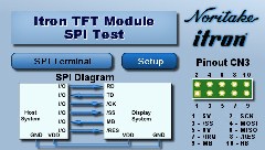
SPI Interface Test Project
|
|
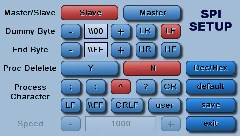
This application allows you to test SPI Interface. You can change various options in the SPI setup. You can communicate between modules using the available keyboard and SPI interface.
|
|
Designer: ITRON Available for 4.3", 5.7", 7.0" : Download Zip File
|
|
|
|
|
|
|
|
Update Information |
Version |
Title |
Date |
Details |
49.58 |
SPI |
07 Sep 15 |
|
* Fixed LSB first option (bit reversal)
|
|
49.51 |
SPI Zero Inter-byte Delay |
20 Feb 14 |
|
* Modified handling of SPI transmit data in slave mode to allow zero inter-byte delay.
|
|
49.51 |
Problem when Port Encode Not Specified |
21 Jan 14 |
|
* A problem was found when the port encode was not being specified, the default should be Ascii Text but was being left undefined.
eg
SETUP( RS2 )
{
... settings ...
encode = s; // If no encode then an error can occur.
}
* This is now fixed.
|
|
49.44 |
Nesting of priority INT()s |
09 Oct 13 |
|
New functionality has been added to support nesting of priority INT()s, ie a priority interrupt can be interrupted by another priority interrupt with a higher priority (this is now the default behaviour).
A system setup variable has been added to disable this functionality.
SETUP(SYSTEM){ intNest = y | n; } // default = y;
For 'y', priority INT()s can be interrupted by higher priority INT()s
For 'n', priority INT()s run to completion, then the highest pending priority INT() is processed next.
|
|
49.44 |
Real Time (Priority) Interrupts |
09 Oct 13 |
|
This issue has been resolved. A problem was found with the operating systems' nested interrupt handler. New functionality has been implemented and tested.
Nesting of priority INT()s has also been added - see TFT Improvement
|
|
49.37 |
Serial Port Buffer Resizing |
10 Jun 13 |
|
* Added the ability to increase size of receive and transmit buffers.
> When a buffer size is increased then the old buffer is discarded (memory is not freed) and a new block of memory is allocated for the new buffer. Read and write pointers are reset and all data is flushed.
* Decreasing a buffer's size has no effect.
* The following ports are affected: RS2, RS4, AS1, AS2, DBG, USB, I2C, SPI
|
|
49.37 |
Losing Serial Interrupts with ''proc'' |
10 Jun 13 |
|
A new INT() processing scheme has been written which has abandoned a "counter" method and instead checks to see if there are any further "packets" waiting to be processed when the INT() command is run.
The old scheme made use of a counter which was incremented in the "hardware" interrupt handler when a packet was received and then decremented when a LOAD(buf,port); was performed from the INT() function. It had been found that the counter can get out of sync with the packets being received and hence packets are left in the receive buffer when the counter has a value of zero.
The new method, sets a task flag in the "hardware" interrupt handler to say a packet has been received. The INT() function then reads the packet when the LOAD(buf,port); command is used and then checks to see if there is another complete packet in the receive buffer. If there is, then the INT() function is called again, and so on, until there are no more complete packets and then the INT() is exited and normal processing resumes.
|
|
49.37 |
Serial Ports - use with d16l, d16m, d32l, d32m, h16l, h16m, h32l, h32m |
10 Jun 13 |
|
Corrected output for d16l, d16m, d32l, d32m, h16l, h16m, h32l, h32m when source is text variable.
|
|
49.19 |
I2C/SPI - Amended IRQ function to support multiple module connection. |
05 Oct 12 |
|
Amended IRQ function to support multiple module connection
Options:
N = No function
L = Enabled (always set to output, goes LOW when data is available to read, same as Y)
H = Enabled (always set to output, goes HIGH when data is available to read)
B = Buffered (set to input in idle state, output / LOW when data is available to read)
|
|
49.16 |
SPI Master - Added master functionality. |
14 Sep 12 |
|
Added master functionality.
* The recieve buffer is reset before each data transmit.
* If data receive is handled via an INT then only data not equal to the 'end' value triggers an interrupt event.
|
|
49.16 |
SPI - Added 'irq' parameter to setup. |
14 Sep 12 |
|
Added 'irq' parameter to setup. Options are Y/N. Default is Y. When Y pin 7 of CN3 is configured as output and is normally high. It goes low when data is loaded into TX buffer and returns high when TX buffer is empty.
|
|
47.04 |
SPI Interrupt - Bug fix in SPI interrupt handling. |
26 Jul 11 |
|
Bug fix in SPI interrupt handling.
|
|
44.00 |
SPI - Changed SPI to use Atmel SPI peripheral rather than SSC |
20 May 11 |
|
Changed SPI to use Atmel SPI peripheral rather than SSC
Only slave mode is functional (receive and transmit)
/IRQ is driven LOW when data is present in transmit buffer
Setup parameters :
set : SHF / SRH / SLR / SFL / MHFxxxx / MRHxxxx / MLRxxxx / MFLxxxx
where xxx is speed
active : N = none / S = slave / M = master
mode : LR or RL = idle low, rising edge / FL or LF = idle low, falling edge /
HF or FH = idle high, falling edge / RH or HR = idle low, rising edge
end : \\xx = value sent when tx buffer is empty
dummy : \\xx = value is ignored, used for receiving data from the module
speed : 400 to 90000 used in master mode to specify bit rate in khz
rxf : N = none, H = hardware handshake
rxo : M = msb first, L = lsb first
txo : M = msb first, L = lsb first
rxb, txb, rxi, txi, encode, proc, procdel same as other ports
|
|
32.00 |
SPI Slave Input - SPI slave mode receive only added. |
14 Oct 10 |
|
SPI slave mode receive only added (further testing required
|
|
|
|