|
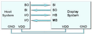
CMOS Asynchronous
Interfaces - AS1, AS2, DBG (3v3 level)
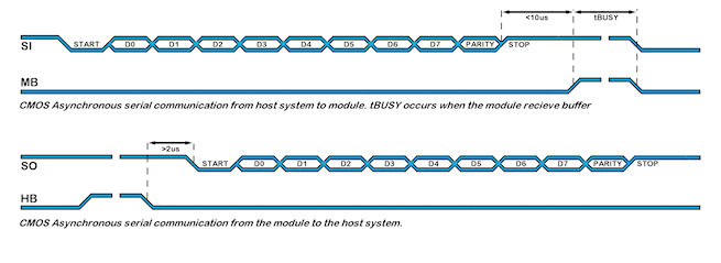
The asynchronous communication speed and parity can be set with the setup
commands. The host busy input (HB) stops the module from sending data
to the host. Equally the module busy input MB should be tested by the host.
The use of the HB and MB busy lines are optional, and can be
connected together if not required.
The AS2 interface is common with the RS4 interface if fitted (-K611/-K618)
RS485 3V3 when RS422 transceiver not fitted
The DBG interface on CN6 is also used to reset hold the module in factory
mode at power on when pin3 (DRRXD) and pin4 (DTXD) are connected. |
 |
 |
|
|
|
|
|
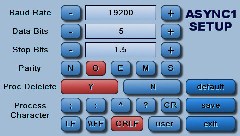
AS1, AS2, DBG set up parameters |
setup(AS1)
//can setup AS1, AS2 or DBG
{
set="96NC";
//quick set up combination "48, 96, 192, 384, 768, 1150 with parity N,
O, E and Command option".
}
setup(AS1)
//can setup AS1, AS2 or DBG
{
//user must test the application to establish the maximum viable baud rate.
baud=38450; //num = 110 to
6,250,000. Any value can be set
to allow trimming for deviating clocks i.e. 38450
data=7;
//num = 5, 6, 7, 8
stop=2;
//num = 1, 15, 2 - note 15 is 1.5 bits
parity=N;
//first letter of Odd, Even, None,
Mark, Space
rxi=Y;
//set receive buffer
interface as active (Y), a command processing source (C) or disable (N).
Default = N
proc=�;�;
//process on receive
termination character(s). See below
procDel=Y;
//remove or keep the termination character(s)
before processing
procNum=5; //interrupt on n bytes received
as alternative to proc and procDel.
rxb=8246;
//set size of
receive buffer in bytes. Default = 8192 bytes, maximum 256K bytes.
txi=Y;
//set transmit
buffer interface as active (Y), to echo command processing (E) or disable
(N)
txb=8246;
//set size of
transmit buffer in bytes. Default = 8192 bytes
encode=s; //set s=ASCII,
w=UNICODE, m=UTF8 or use sr specifying raw text bytes and sd for raw data.
flow=N;
//none (N), hardware RTS/CTS
or DTR/DSR (H), software XON/XOFF (S).
}
|
Data Processing Interrupt Characters
Termination characters can
be specified to generate an interrupt to process a string of data.
The
proc
parameter is used in the port setup to define the termination characters.
proc = all;
<- trigger on all received characters
proc = CRLF;
<- trigger on a CR followed by LF (0Dh 0A)
proc = CR;
<- trigger on CR (0Dh)
...in command mode rxi=C this is fixed
proc = LF;
<- trigger on LF (0Ah)
proc = NUL;
<- trigger on NUL (00h)
proc = \\xx;
<- trigger on xxh (hex value)
proc = "ABCD";
<- string in format defined by SYSTEM encode param
proc = "\\xx\\xx";
<- string in format defined by SYSTEM encode param
When
sending commands (rxi=C) to the module, processing only occurs when \\0D or 0D
hex is received.
Example: TEXT(MyText,"Hello World");;\\0D
Data Encode Modes
encode=s; 8 bit ASCII data. Codes
00-1F and 80-FF are converted to ASCII "\\00" - "\\1F",
"\\
encode=sr;
8 bit data. Codes 00-07 are processed as cursor
commands. 20-FF are processed as ASCII+ data
encode=sd; 8bit data. All bytes are
processed as raw data.
Other mode styles are available:
D8M - 8 bit data with
U16's, U32's etc output most significant byte first - same as sd
D8L - 8 bit data with
U16's, U32's etc output least significant byte first
D16M
- 16 bit data with bytes processed as most significant byte first -
interrupt occurs after two bytes - same as wd
D16L - 16 bit data with bytes
processed as least significant byte first - interrupt occurs after
two bytes
D32M - 32 bit data with
bytes processed as most significant byte first - interrupt occurs after
four bytes - same as md
D32L - 32 bit data with
bytes processed as least significant byte first - interrupt occurs after
four bytes
Using hex pairs
sh or h8m or h8l = Ascii-Hex Char x 2 = U8; eg "A8" ->
\\A8
h16m = Ascii-Hex Char x 4 = U16 (Most significant hex-pair first) eg "ABCD" ->
\\ABCD
h16l = Ascii-Hex Char x 4 = U16 (Least significant hex-pair first) eg "ABCD"
-> \\CDAB
h32m = Ascii-Hex Char x 8 = U32 (Most significant hex-pair first) eg
"12345678" -> \\12345678
h32l = Ascii-Hex Char x 8 = U32 (Least significant hex-pair first) eg
"12345678" -> \\78563412
Dot Operator
Parameter can be updated using the dot operator
LOAD(AS1.baud,19200);
//can load AS1, AS2 or DBG
LOAD(AS1.proc,"CR");
//can load AS1, AS2 or DBG
|
Example
setup(AS1)
//can setup AS1, AS2 or DBG
{
set="96NC"
//quick set up combination "48, 96, 192, 384, 768, 1150 with parity N,
O, E and Command option".
}
PAGE( PageName, PageStyle)
{
POSN(100,100);
TEXT ( RecvTxt, "Example", stRecvTxt);; //show received ASCII data on screen
....
....
INT( ASerRxInt, AS1RXC, SerRxEvent ); //Used when rxi=Y
}
FUNC( SerRxEvent )
{
LOAD( Var, AS1 ); // Must read AS1 to clear interrupt
TEXT (
RecvTxt, Var);; //show received ASCII data on screen and refresh.
To update, no style is specified.
}
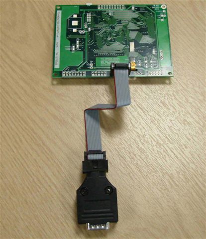
CANBUS Adaptor
When attaching a CANBUS adaptor type EMCBK33 to CN3 using a 10 way IDC
cable, the connector is fitted to the backside of the module and the
following set up is required to match the default settings in the adaptor.
setup(AS1)
{
baud=38400;
//num = 110 to 115200. Any value can be set
to allow trimming for deviating clocks i.e. 38450
data=8;
//num = 5, 6, 7, 8
stop=1;
//num = 1, 15, 2 - note 15 is 1.5 bits
parity=N;
//first letter of Odd, Even, None,
Mark, Space
rxi=C;
//set receive buffer
interface as active (Y), a command processing source (C) or disable (N).
Default = N
encode=sr;
//set s=ASCII, w=UNICODE, m=UTF8 or use sr, wr
and mr specifying raw data bytes.
flow=H;
//none, hardware RTS/CTS
or DTR/DSR, software XON XOFF
}
The default receive address for the adaptor is ID=155h with 11bit or 29bitID
packets accepted (2.0a or 2.0b spec)
All bytes are received on AS1 with 1 to 8 bytes of data.
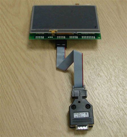
The transmit ID is also 155H. with data sent via AS1 with data length
of 1.Connection to an iSMART TFT is shown below.
|
|
Active |
|
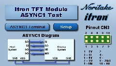
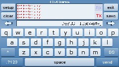
ASYNC1 Interface Test Project
|
|
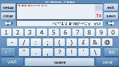
This application allows you to test ASYNC1 Interface. You can change various options in the ASYNC1 setup. You can communicate between two modules using the available keyboard and ASYNC1 interface.
|
|
Designer: ITRON Available for 4.3", 5.7", 7.0" : Download Zip File
|
|
|
|
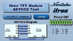
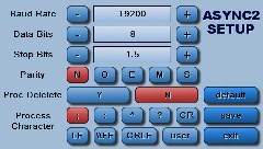
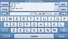
ASYNC2 Interface Test Project
|
|
This application allows you to test ASYNC2 Interface. You can change various options in the ASYNC2 setup. You can communicate between two modules using the available keyboard and ASYNC2 interface.
|
|
Designer: ITRON Available for 4.3", 5.7", 7.0" : Download Zip File
|
|
|
|
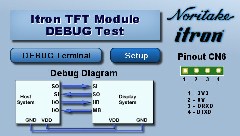
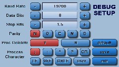
DEBUG Interface Test Project
|
|
This application allows you to test DEBUG Interface. You can change various options in the DEBUG setup. You can communicate between two modules using the available keyboard and DEBUG interface.
|
|
Designer: ITRON Available for 4.3", 5.7", 7.0" : Download Zip File
|
|
|
|
|
|
|
|
Update Information |
Version |
Title |
Date |
Details |
49.51 |
KEYIO and Serial Port H/W Flow Control Can Stop Transmission |
18 Feb 14 |
|
* Fixed potential problem with transmit being disabled when keyio enabled and hardware flow control disabled. This affected RS232, RS485, ASYNC1, ASYNC2.
* The flow control setting is now correctly checked in the KEYIO handler.
|
|
49.51 |
Problem when Port Encode Not Specified |
21 Jan 14 |
|
* A problem was found when the port encode was not being specified, the default should be Ascii Text but was being left undefined.
eg
SETUP( RS2 )
{
... settings ...
encode = s; // If no encode then an error can occur.
}
* This is now fixed.
|
|
49.44 |
Nesting of priority INT()s |
09 Oct 13 |
|
New functionality has been added to support nesting of priority INT()s, ie a priority interrupt can be interrupted by another priority interrupt with a higher priority (this is now the default behaviour).
A system setup variable has been added to disable this functionality.
SETUP(SYSTEM){ intNest = y | n; } // default = y;
For 'y', priority INT()s can be interrupted by higher priority INT()s
For 'n', priority INT()s run to completion, then the highest pending priority INT() is processed next.
|
|
49.44 |
Real Time (Priority) Interrupts |
09 Oct 13 |
|
This issue has been resolved. A problem was found with the operating systems' nested interrupt handler. New functionality has been implemented and tested.
Nesting of priority INT()s has also been added - see TFT Improvement
|
|
49.39 |
Updating Firmware - ''NAND Error - need physical block'' Error |
13 Jun 13 |
|
When boot code is updated via a serial link (RS2, USB, AS1 etc), the error "NAND Error - need physical block" is reported.
It was found that the boot block range check was invalid when searching for "good" blocks. Fix available in V00.49.39
|
|
49.37 |
Serial Port Buffer Resizing |
10 Jun 13 |
|
* Added the ability to increase size of receive and transmit buffers.
> When a buffer size is increased then the old buffer is discarded (memory is not freed) and a new block of memory is allocated for the new buffer. Read and write pointers are reset and all data is flushed.
* Decreasing a buffer's size has no effect.
* The following ports are affected: RS2, RS4, AS1, AS2, DBG, USB, I2C, SPI
|
|
49.37 |
Modbus - Additional Functionality |
10 Jun 13 |
|
* Added support for function codes 5/6 (write single coil / register).
* Added alternative means of accessing register / coil data using 2 dimensional array. 2 dim mode is automatically selected if MB_xxx_REGS / MB_xxx_COILS points to a 2 dim array. In this case the first dimension specified the address and the second holds the data. The coil array must be U16 in 2 dim mode. 2 dim mode is not fully tested.
|
|
49.37 |
Losing Serial Interrupts with ''proc'' |
10 Jun 13 |
|
A new INT() processing scheme has been written which has abandoned a "counter" method and instead checks to see if there are any further "packets" waiting to be processed when the INT() command is run.
The old scheme made use of a counter which was incremented in the "hardware" interrupt handler when a packet was received and then decremented when a LOAD(buf,port); was performed from the INT() function. It had been found that the counter can get out of sync with the packets being received and hence packets are left in the receive buffer when the counter has a value of zero.
The new method, sets a task flag in the "hardware" interrupt handler to say a packet has been received. The INT() function then reads the packet when the LOAD(buf,port); command is used and then checks to see if there is another complete packet in the receive buffer. If there is, then the INT() function is called again, and so on, until there are no more complete packets and then the INT() is exited and normal processing resumes.
|
|
49.37 |
Serial Ports - use with d16l, d16m, d32l, d32m, h16l, h16m, h32l, h32m |
10 Jun 13 |
|
Corrected output for d16l, d16m, d32l, d32m, h16l, h16m, h32l, h32m when source is text variable.
|
|
49.16 |
UART Enable / Disable - Added active=Y/N parameter to RS2/RS4/AS1/AS2/DBG/USB setup. |
14 Sep 12 |
|
Added active=Y/N parameter to RS2/RS4/AS1/AS2/DBG/USB setup. Default is Y for backward compatibility. Allows the associated interface port pins to be disabled by using LOAD(port.active, N);
|
|
|
|