|
Rotary Encoder with Push
Switch
|
The MCB40A rotary encoder with
push switch accessory can be connected to CN7 on the TFT module. The
rotary encoder can be used to control a predefined variable (ENCVAL1 OR
ENCVAL2) which when used in functions can control numerous events such as
scrolling through a list to incrementing a value. The additional push switch
on the MCB40A allows for a function to be called on the key press allowing
for the rotary encoder to act as a menu select control where you can scroll
through a list and press the switch to select an item.
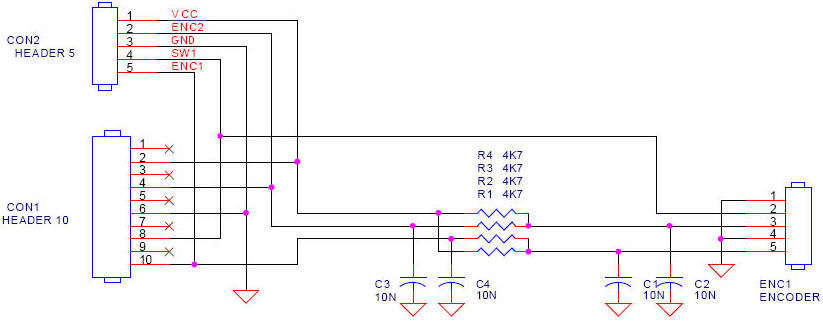
Each rotary encoder uses 5 pins allowing for two separate MCB40A to be
connected to a single 10 way IDC cable.
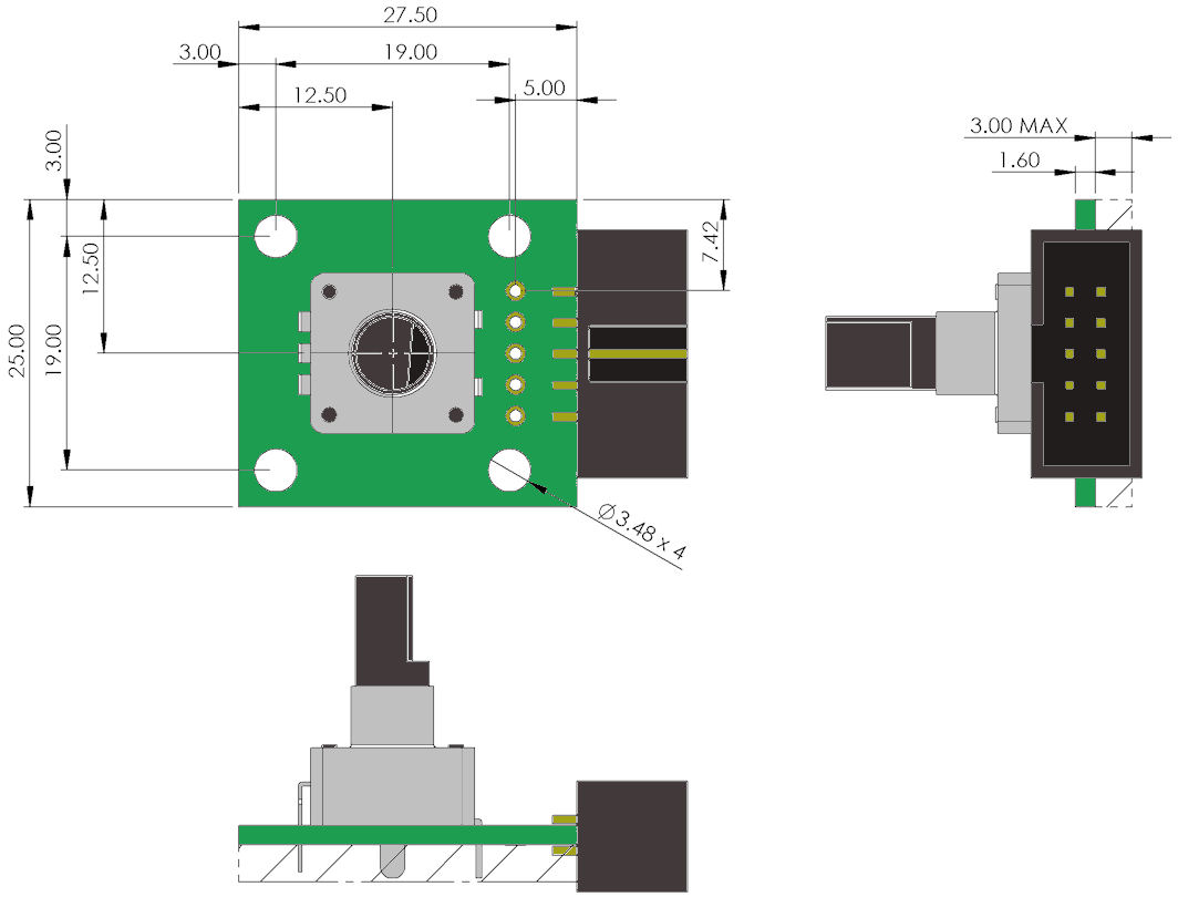
 2D mechanical
 View
Photograph View
Photograph
|
Pin 1 |
1 |
2 |
3 |
4 |
5 |
|
Con 1 |
- |
- |
- |
- |
- |
|
Con 2 |
High |
Port B |
Low |
Switch |
Port A |
|
Pin 1 |
2 |
4 |
6 |
8 |
10 |
|
Con 1 |
High |
Port B |
Low |
Switch |
Port A |
|
|
Rotary Encoder Properties
|
ALPS - EC12E1224402 - ENCODER, VERTICAL, 12
DET, 12PPR+SW
|
|
No. of Channels |
2 |
|
Connector Type |
Pin |
|
Dielectric Strength VAC |
50V |
|
Encoder Resolution |
12 |
|
External Depth |
14mm |
|
External Length / Height |
6mm |
|
External Width |
13.2mm |
|
No. of Detents |
12 |
|
No. of Pulses Per Revolution |
12 |
|
Operating Temperature Max |
+70�C |
|
Operating Temperature Min |
-10�C |
|
Operating Temperature Range |
-10�C to +70�C |
|
Pulse Output Count |
12 |
|
Rotation Mechanical Angle |
360� |
|
Rotational Life Cycles |
30000 |
|
Series |
EC12 |
|
Shaft Diameter |
6mm |
|
Shaft Length - Metric |
8.5mm |
|
Supply Current |
0.5mA |
|
Supply Voltage Max |
5VDC |
|
Supply Voltage V DC |
50V |
|
Torque Max |
20mN-m |
|
Torque Min |
3mN-m |
|
Type |
Vertical |
Rotary Encoder Setup
SETUP(ENC)
{
active = 1/2/12; // N=none active, 1=enc1 active, 2 = enc2 active, 12 = both
active
a1 = \\xx; // port number for enc1 A channel
b1 = \\xx; // port number for enc1 B channel
a2 = \\xx; // port number for enc2 A channel
b2 = \\xx; // port number for enc2 B channel
debounce1 = n; // debounce time in ms for enc1 (1 - 100ms)
debounce2 = n; // debounce time in ms for enc2 (1 - 100ms)
timeout1 = n; // timeout period in ms for enc1 (1 - 1000ms)
timeout2 = n; // timeout period in ms for enc2 (1 - 1000ms)
mode1 = n; // encoder type (1 or 2) for enc1
mode2 = n; // encoder type (1 or 2) for enc2
}
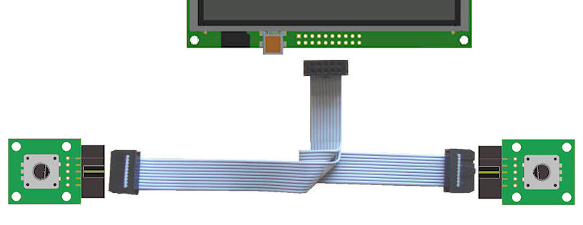
Connection and Pinout Example for Connecting
Two Rotary Encoders
To use one ribbon cable with two Rotary Encoders you will need to set up a
ribbon cable as pictured below.
You will then need to connect the first MCB40A to the
connector on the right (picture below) this rotary encoder will use K01,K03,K05,K07,K09
The second MCB40A will need to be inverted, in the picture the
ribbon cable has been twisted to do this.
(the ridge on the left connector will need to be removed so that it can plug into
the MCB40A) this MCB40A will use K00,K02,K04,K06,K08.
You will then need to connect the top connector to CN7 from K00-K09.
Below is an example code and pinout for two rotary encoders
on a single 10 way IDC cable connected to the K00-K09 using the ribbon cable
as pictured above.
| |
High |
Low |
Port A |
Port B |
Switch |
|
MCB40A (1) |
K01 |
K05 |
K09 |
K03 |
K07 |
|
MCB40A
(2) |
K08 |
K04 |
K00 |
K06 |
K02 |
Example Code
SETUP(KEYIO) {active=\\0003ff; inp = \\000084; trig = \\000084; edge = \\000000; }
SETUP(ENC)
{
active = 12; // N=none active, Y or 1=enc1 active, 2 = enc2 active, 12 = both active
a1 = \\09; // port number for enc1 A channel
b1 = \\03; // port number for enc1 B channel
a2 = \\00; // port number for enc2 A channel
b2 = \\06; // port number for enc2 B channel
debounce1 = 2; // debounce time in ms for enc1 (1 - 100ms)
debounce2 = 2; // debounce time in ms for enc2 (1 - 100ms)
mode1 = 1; // encoder type (1 or 2) for enc1
mode2 = 1; // encoder type (1 or 2) for enc2
}
LOAD(K01,1);
LOAD(K08,1);
STYLE(ps, Page) {back = black;}
STYLE(ts, Text) {font = Ascii32; col = white;}
INT(change1, ENC1, fnc1);
INT(clear1, K07, fnc3);
INT(change2, ENC2, fnc2);
INT(clear2, K02, fnc4);
PAGE(page1,ps)
{
POSN(120,136);
TEXT(t1,"0",ts);
POSN(360,136);
TEXT(t2,"0",ts);
}
FUNC(fnc1){ TEXT(t1,ENCVAL1);; }
FUNC(fnc2){ TEXT(t2,ENCVAL2);; }
FUNC(fnc3){ LOAD(ENCVAL1,0);TEXT(t1,ENCVAL1);; }
FUNC(fnc4){ LOAD(ENCVAL2,0);TEXT(t2,ENCVAL2);; }
SHOW(page1);
|