|
|
Keyboard and I/O Interfacing |
Keyboard Control
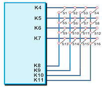
24 I/O lines (K0-K23) can be configured to scan a key matrix with up to
144 keys configured using the setup commands for I/O control. When a key is
pressed, a function can
be initiated using a key command.
Dual key presses are supported to enable SHIFT functionality.
No diodes are required in the key matrix for dual key operation making it ideal for low cost
membrane keyboards.
NOTE: The KEY() function requires Kn connects to Km.
To use Kn connects to GND, use
an INT(Name,Kn,function); command
|
 |
setup(keyio)
{
active=\\000000FF; //high is active �\\00000000� >�\\7FFFFFFF�, default is
inactive
keyb=\\000000FF; //high is scanned keyboard connection
�\\00000000�>"\\7FFFFFFF�
pullup=\\FFFFFFFF; //introduced in v49.06 to allow input pull up resistors
to be set ON=1 and OFF = 0
}
STYLE(stkeypad,key)
{
type=touch; //specify 'touch' screen or external 'keyio'
debounce=250; //Specify the time delay to allow external key press to
stabilise in milliseconds.
delay=1000; //Specify the time delay before key auto repeat occurs in
milliseconds. 0=off.
repeat=500; //Specify the repeat period if the key is held down in
milliseconds
action = D; //Specify D or Down and U or Up and C for change.
curRel=CC; //specify touch key placement relative to cursor. CC Centre
Centre , TC Top Centre,
} //BC Bottom Centre, LC Left Centre, RC Right Centre, TL Top Left,
// BL Bottom Left, TR Top Right, BR Bottom Right
Define the keys in a PAGE the same as touch keys
KEY(ExtKey,ExFunc,K4,K9,stkeypad); This external key calls the function when
K7 and K16 connect.
|
I/O Control
The module contains simple Input and Output functions for the 24 I/O
lines (K0-K23).All inputs include an optional pull-up resistor ~50K-120K in
value. The outputs can source ~1mA and sink ~3mA.
Certain I/O have expanded functions for customization.
When using an input it is recommended to set the pull-ups as ON to stop the
pins floating.
At RESET or POWER ON, the I/O ports are initially set as inputs and pulled
high by 70K-175K.
With the exception of K08,K10,K14 and K15 which are set as outputs and are
driven low.
The IO ports will remain in this state until an interface setup is processed
K30 is the highest
order bit and K0 the lowest.
NOTE: The ports K00 to K30 have series resistors and capacitors to GND.
Please check each model hardware specification for the specified values.
To use Kn connects to GND, use an INT(Name,Kn,function); command
|
 |
|
keyio K00-K30 |
31 bits of
user i/o and keyboard
operational |
setup(keyio)
{
active=\\000000FF;
//high is
active �\\00000000� >�\\7FFFFFFF�, default is inactive
inp=\\0000000C;
//high is
input, low is output �\\00000000� >�\\7FFFFFFF�
trig=\\00000001;
//high is
trigger interrupt �\\00000000� >�\\7FFFFFFF� as defined by edge.
1=trigger .
edge=\\00000000;
//high is
rising edge, low is falling edge �\\00000000� >�\\7FFFFFFF�
keyb=\\00000FF0;
//high is
scanned keyboard connection �\\00000000�>"\\7FFFFFFF�
pullup=\\7FFFFFFF;
//introduced in v49.06 to allow input pull up resistors to be set ON=1 and
OFF = 0
}
Single bit variables can be set and tested K00, K01, K02...K30 once
enabled
8 bit variables can be set and tested KA, KB, KC, KD, KE once enabled
KA =
K07,K06,K05,K04,K03,K02,K01,K00
KB = K15,K14,K13,K12,K11,K10,K09,K08
KC = K14,K12,K10,K08,K06,K04,K02,K00
KD = K15,K13,K11,K09,K07,K05,K03,K01
KE = K23,K22,K21,K20,K19,K18,K17,K16
If another function is enabled which uses an I/O pin, the keyio
functionality for the pin is disabled automatically.
|
example usage to set
LOAD(K01,1); set K1 to high
LOAD(K02,0); set K2 to low
LOAD(KA,\\02); set K0,K2-K7 low and K1 high
LOAD(myVar,K01) load port into user variable
LOAD(myVar,KA) load 8bit port into user variable
example usage with interrupt
SETUP(keyio)
{
active=\\00000001; // set K00 to be active
inp=\\00000001; // set K00 as input
trig=\\00000001; // enable trigger interrupt on K00
edge=\\00000000; // set to trigger in falling edge
}
PAGE(mypage,pagestyle)
{
//set up entities or keys on page
INT(myInt,K00,myEvent); // setup interrupt to call �myEvent� on every
K00 event
//rest of page
}
FUNC(myEvent) // This function is called each time a falling edge is
detected on K00
{
// some actions
}
The current firmware requires the K parameter to be 3 characters in length
|
|
rotary
encoder control |
|
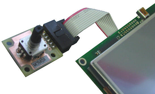
2 encoders to be connected
to any available I/O ports.
The rotary encoders available on the Accessories page allow a 10way IDC
cable to control 2 encoders with center push switches.
* System variables ENCVAL1 or ENCVAL2 are type S32 and hold the current
count values for each encoder.
* LOAD(ENCVAL1,n); presets encoder variable value to required number n.
* The value of ENCVALn is decremented by the number of clicks left and
incremented by the number of clicks right.
* Timeout specifies the time from the last rotation event until the INT is
triggered.
SETUP(ENC)
{
active = 1/2/12; // N=none active, 1=enc1 active, 2 = enc2 active, 12 = both
active
a1 = \\xx; // port number for enc1 A channel
b1 = \\xx; // port number for enc1 B channel
a2 = \\xx; // port number for enc2 A channel
b2 = \\xx; // port number for enc2 B channel
debounce1 = n; // debounce time in ms for enc1 (1 - 100ms)
debounce2 = n; // debounce time in ms for enc2 (1 - 100ms)
timeout1 = n; // timeout period in ms for enc1 (1 - 1000ms)
timeout2 = n; // timeout period in ms for enc2 (1 - 1000ms)
mode1 = n; // encoder type (1 or 2) for enc1
mode2 = n; // encoder type (1 or 2) for enc2
}
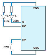
INT(name, ENC1, fnc);
INT(name, ENC2, fnc);
|
|
|
Below is the circuit diagram
of the MCB40A Rotary Encoder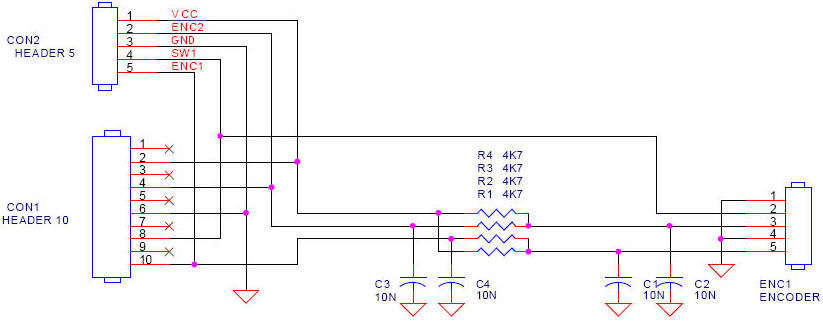
Simple mnu file for 1 rotary
encoder Port A = K01 B = K02 Switch = K00

|
|
I/O counters CNTK00-CNTK30 |
The 31 I/O counters use pre-define variables which can be reset and tested
for value.
The counter uses an unsigned 32bit register (U32) with names CNTKxx where
xx=00 to 30.
They require the I/O to be set as an interrupt but
do not require an associated INT()
command.
Counter increment depends on the rising or falling edge of the interrupt.
The command RESET(CNTK00) resets to zero the I/O counter on K00.
The maximum counter speed is 0-10kHz+ but is dependent on other interrupt
and entity usage. |
|
CNTK00 |
Counter on I/O K00
(CN7) |
|
CNTK01 |
Counter on I/O K01
(CN7) |
|
| |
|
|
CNT29 |
Counter on I/O K29
(CN3) |
|
CNT30 |
Counter on I/O K30
(CN3) |
|
|
|
|
Example
Usage |
IF(CNTK00>300?Func300); //if greater than 300 run function
called Func300
TEXT(K00Text,CNTK00);; //update counter value on page and
refresh screen |
|
|
operational v40 |
|
|
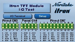
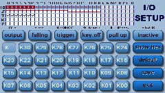
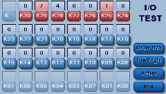
I/O Ports Test Project
|
|
This application allows you to test I/O Ports. You can change various options in the I/O setup and communicate between two modules.
|
|
Designer: ITRON Available for 4.3", 5.7", 7.0" : Download Zip File
|
|
|
|
|
|
|
Update Information |
Version |
Title |
Date |
Details |
49.58 |
KEYIO |
07 Sep 15 |
|
* Added K31 (CNX, pin 15 of CN5)
* Added KF group (K24 to K31)
|
|
00.02.00 |
Support for K31 |
19 Feb 15 |
|
Functionality added for K31 to match K0-K30
|
|
49.49 |
Multiple ''Single Key'' Inputs Not Working |
03 Dec 13 |
|
* Fixed issue with only one single KEY() being processed when multiple single KEY()s existed in the project.
* Also fixed an issue where KEY() was defined but not active in setup causing module crash.
|
|
49.48 |
External I/O Interrupts Being Missed |
21 Nov 13 |
|
* Fixed problem where external interrupts (K00-K30) faster than interrupt function were being missed.
* INT() priority can now be specified for extern key interrupts.
|
|
49.44 |
Nesting of priority INT()s |
09 Oct 13 |
|
New functionality has been added to support nesting of priority INT()s, ie a priority interrupt can be interrupted by another priority interrupt with a higher priority (this is now the default behaviour).
A system setup variable has been added to disable this functionality.
SETUP(SYSTEM){ intNest = y | n; } // default = y;
For 'y', priority INT()s can be interrupted by higher priority INT()s
For 'n', priority INT()s run to completion, then the highest pending priority INT() is processed next.
|
|
49.44 |
Real Time (Priority) Interrupts |
09 Oct 13 |
|
This issue has been resolved. A problem was found with the operating systems' nested interrupt handler. New functionality has been implemented and tested.
Nesting of priority INT()s has also been added - see TFT Improvement
|
|
49.44 |
External Keys Being Missed During Input Comms |
05 Oct 13 |
|
New Key Scan algorithm implemented
|
|
49.43 |
Add Single Key I/O Global Interrupt Capability |
12 Sep 13 |
|
* The KEY interrupt can now be defined globally as well as in a page.
|
|
49.43 |
KEYIO Interrupts Not Working |
12 Sep 13 |
|
* Fixed problems with Key Interrupts operating incorrectly.
|
|
49.42 |
External Keys on Single I/O Port Pin |
06 Sep 13 |
|
* An external key can now be defined using a single I/O port (for use when a switch is connected to either
GND or VDD.
The key is defined as follows :-
KEY(mykey, func, port_number, keystyle);
The KEY is triggered on a falling edge if keystyle action = D, on a rising edge if action = U
The port used for the key must be setup in the setup(keyio) section as active and as an input
Example:
SETUP(KEYIO)
{
active = \\00000001;
inp = \\00000001;
}
STYLE(stKey, KEY)
{
type = keyio;
action = d;
debounce = 10;
delay = 500;
repeat = 100;
}
STYLE(stPg, PAGE) { back = black; }
STYLE(stTxt, TEXT) { font = Ascii16; col = white; }
VAR(cnt, 0, U32);
PAGE(pgTest, stPg)
{
POSN(239, 135);
TEXT(t, "0", stTxt);
KEY(k, fnc, \\00, stKey);
}
FUNC(fnc)
{
CALC(cnt, cnt, 1, "+");
TEXT(t, cnt);;
}
SHOW(pgTest);
|
|
49.42 |
Show/Hide of I/O Interrupts |
06 Sep 13 |
|
* I/O interrupts are now handled the same as other interrupts therefore can now be enabled / disabled via the use of SHOW() / HIDE()
|
|
49.37 |
I/O Setup |
10 Jun 13 |
|
Fixed a problem that occurs when changing port settings such as inp and pullup after initial setup
Reading input port value now always returns 0 if port is set as inactive
|
|
49.14 |
KEYIO - Fixed KEYIO problem affecting LOAD(keyio.param, value);. |
27 Jul 12 |
|
* Fixed KEYIO problem affecting LOAD(keyio.param, value);
|
|
49.08 |
KeyIO - Fixed problem with keyscan. |
11 Jul 12 |
|
Fixed problem with keyscan. Scan is now only performed when both nodes are configured as 'keyb' in the setup.
* Initial values for I/O port configuration now guaranteed
|
|
49.06 |
I/O pullups - Add parameter in KEYIO setup to allow port pullup to be enabled / disabled when used as input. |
29 Jun 12 |
|
Add parameter in KEYIO setup to allow port pullup to be enabled / disabled when used as input.
- Parameter : pullup = \\xxxxxxxx; Default is \\FFFFFFFF (all pullups ON).
|
|
|
|
|