itron SMART TFT Hardware   General Overview + Connector Pin Assignment  
             
Interfaces Memory Accessories
RS232 SD Card Audio
RS485 NAND CANBUS
Async EEPROM Rotary Encoder
SPI USB Host
I2C Design Ethernet
USB Mounting SD Card
External Key + I/O RFI Gaskets
ADC ESD Cables
  PWM Temperature Battery Holder
  BUZZ Precautions  


Hardware
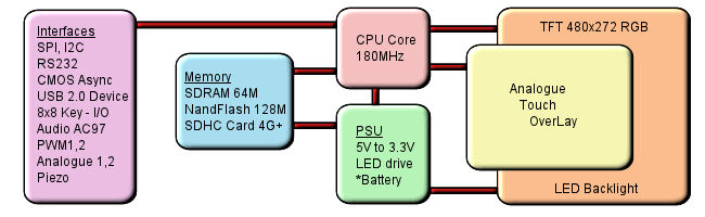
This product has been designed to simplify the implementation of TFT technology into your product yet provide a high level functionality.
The high level text based object oriented command structure, entity library and multi page screen memory allow most of the processing to be undertaken by the TFT module leaving the host CPU to concentrate on the core application processes. This allows proven firmware running on small 8 bit microcontrollers to be modified to drive this TFT with a minimum of work and risk.

*option

Connector Pin Assignment

Connector 1
- RS232 / RS485 / RS422
Back Front

Pin/Cn1

RS232

RS232/485 RS232/422
1   2 2   1   1 NC RT+ T+
2 DTR - R-
3   4 4   3 3 TXD TXD TXD
4 CTS CTS CTS
5   6 6   5 5 RXD RXD RXD
6 RTS RTS RTS
7   8 8   7 7 DSR - R+
8 NC RT- T-
9   10 10   9 9 GND GND GND
10 5V 5V 5V

Connector 2
- Supply / Piezo


Pin/Cn2

Supply/Piezo
          1 5V
2 /Pz

3

2 1 3 0V

Connector 3
- I2C / Async / SPI / IO ports

Back Front

Pin/Cn3

I2C Async SPI

IO ports

    A + B VBB = 5V VBB = 5V VBB = 5V VBB = 5V
B + C VBB = 3V3 VBB = 3V3 VBB = 3V3 VBB = 3V3
1   2 2   1 1 VBB VBB VBB VBB
2 SCL - SCK K24
3   4 4   3 3 - SI /SS K25
4 SDA - MOSI K26
5   6 6   5 5 0V 0V 0V 0V
6 /IRQ - MISO K27
7   8 8   7 7 - SO /IRQ K28
8 /RES /RES /RES /RES
9   10 10   9 9 - MB MB K29
10 - HB HB K30
Jumper ABC are solder pads. Jumper terminal B connects to pin 1 - VBB
When 3V3 is selected pin 1 can only be used as an output

Connector 4
 - ADC / PWM / Audio / IO ports

Back Front  

Pin/Cn4

ADC PWM Audio

IO ports

            A + B VBB = 5V VBB = 5V VBB = 5V VBB = 5V
B + C VBB = 3V3 VBB = 3V3 VBB = 3V3 VBB = 3V3
1   2 2   1 1 AN1 - - K16
2 AN2 - - K17
3   4 4   3 3 0V  0V 0V 0V
4 VBB VBB VBB VBB
5   6 6   5 5 - PWM1 - K18
6 - PWM2 - K19
7   8 8   7 7 - - ATX K20
8 - - ARX K21
9   10 10   9 9 - - ACK K22
10 - - AFS K23
Jumper ABC are solder pads. Jumper terminal B connects to pin 4 - VBB
When 3V3 is selected pin 1 can only be used as an output

Connector 5
- USB / SD Card
Back Front  

Pin/Cn5

USB SD Card
1   2 2   1 1 - DA2
2 - DA3
3   4 4   3 3 - CDA
4 - 3V3
5   6 6   5 5 - CK
6 - 0V
7   8 8   7 7 - DA0
8 - DA1
9   10 10   9 9 - 0V
10 - CD
11   12 12   11 11 0V -
12 5V -
13   14 14   13 13 DM -
14 DP -
15   16 16   15 15 CNX -
16 0V -

Connector 6
- Debug

Pin/Cn6

Debug

          1 3V3
2 0V
4 3 2 1 3 DRXD
4 DTXD

Connector 7
- IO ports / Async2 / PWM
Back Front

Pin/Cn7

IO ports

Async 2

PWM

1   2 2   1   1 5V 5V 5V
2 0V 0V 0V
3   4 4   3 3 3V3 3V3 3V3
4 0V 0V 0V
5   6 6   5 5 K0 TXD -
6 K1 RXD -
7   8 8   7 7 K2 - -
8 K3 - -
9   10 10   9 9 K4 - -
10 K5 - -
11   12 12   11 11 K6 - -
12 K7 - -
13   14 14   13 13 K8 - -
14 K9 - PWM3
15   16 16   15 15 K10 - -
16 K11 - -
17   18 18   17 17 K12 - -
18 K13 - -
19   20 20   19 19 K14 - -
20 K15 - -

Connector 8
- USB
   

Pin/Cn8

USB

  1 5V
2 DM
3 DP
4 CNX*
 

1 2 3 4 5

  5 0V
*Not Function - For future use

Connector 9
- Micro SD Card
 

Pin/Cn9

Micro SD Card
          1     1 DA2
    2 DA3
    3 CDA
    4 3V3
    5 CK
    6 0V
    7 DA0


    8 DA1
  Micro SD Card Socket    9 0V
      10 CD

Connector 12
- Async RS4 (when 485 not fitted)

Pin/Cn12

Async RS4

          1 TXD
2 0V
4 3 2 1 3 RXD
4 5V

Connector 13
- Keyboard
   

Pin/Cn13

Keyboard

          1 0V
2 AD0
5 4 3 2 1 3 AD3
4 AD1/AD2
              5 AD1/AD2

Connector 15
- USB
   

Pin/Cn15

USB

          1 5V
2 DM
5 4 3 2 1 3 DP
4 CNX
              5 0V