|
I2C
Interface
|
|
TWI / I2C
Interface - I2C (3v3 level)
The I2C interface operates as a slave either in �slave receive� or �slave
transmit� mode with a user defined address set in the I2C setup. Receive
(i2c.rxb) and transmit (i2c.txb) buffers of 8192 bytes are created which can
be cleared and set by the command processor. An end byte indicating empty
buffer can be set. |
|
The user must fit 10K pull up resistors to SDA and SCL somewhere on their
I2C bus
.jpg)
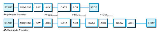
Single Slave |
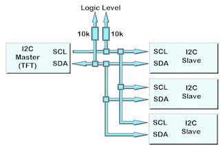
Multiple Slave |
 |
|
|
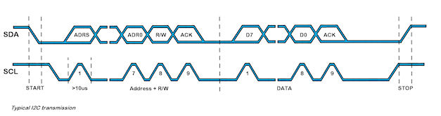
An overview of
how TWI / I2C communicates
A START condition is signalled by driving SDA low while SCL is high. A STOP condition is signalled by
driving SDA high while SCL is high. After a START condition is
detected followed by address + R/W bit, the command / data bytes are stored
in a buffer size specified in the setup. The module will pull SDA low during the 9thclock cycle
of a data transfer to acknowledge the receipt of a byte. Additional data may
be sent providing
the host receives an Ack. If the host has not detected an Ack the data
transfer must be started again by providing a STOP and START condition and
address + R/W bit low. When reading an I2C packet must be sent with address+1
read the data bytes from the I2C transmit buffer.
|
|
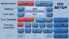
twi / i2c set up parameters |
|
setup(i2c)
{
set = "C3E";
//quick set up of
I2C - Slave with Command and Address
}
setup(i2c)
{
addr="\\3E"; //set the address pair of the TFT module
(Slave mode) in HEX code, range \\01-\\7F
end="\\00"; //byte returned when
no data left in display's i2c transmit buffer
active=S; //set as Master (M)
or
Slave (S) or disabled (N). Default = N
speed=100; //set transmit speed
value in kilobits/sec from 20 to 400 for master mode. Default = 100
rxi=Y; //set receive buffer
interface as active (Y), a command processing source (C) or disable (N).
Default = N
proc=�;�; //process on receive termination character(s)
procDel=Y;
//remove or keep the termination character(s)
before processing
procNum=5; //interrupt on n bytes received
as alternative to proc and procDel.
encode=s; //set s=ASCII, w=UNICODE, m=UTF8 or use sr specifying raw text bytes and sd
for raw data.
rxb=8192; //set size of
receive buffer in bytes. Default = 8192 bytes
txi=Y;
//set transmit
buffer interface as active (Y), to echo command processing (E) or disable
(N)
txb=8192;
//set size of
transmit buffer in bytes. Default = 8192 bytes
}
When sending data in a protocol to the TFT module in slave mode, set up an
interrupt either globally or in a PAGE for context functionality.
INT(I2Crecv,I2CRXC,I2Cfunc);
NB: The address specified in
setup is only processed and used when the TFT module is in slave mode. The
address in master mode is specified using the LOAD command. |
Data Processing Interrupt Characters
Termination characters can
be specified to generate an interrupt to process a string of data.
The
proc
parameter is used in the port setup to define the termination characters.
proc = all;
<- trigger on all received characters
proc = CRLF;
<- trigger on a CR followed by LF (0Dh 0A)
proc = CR;
<- trigger on CR (0Dh)
...in command mode rxi=C this is fixed
proc = LF;
<- trigger on LF (0Ah)
proc = NUL;
<- trigger on NUL (00h)
proc = \\xx;
<- trigger on xxh (hex value)
proc = "ABCD";
<- string in format defined by SYSTEM encode param
proc = "\\xx\\xx";
<- string in format defined by SYSTEM encode param
When sending commands (rxi=C) to the module, processing only occurs when \\0D or 0D
hex is received.
Example: TEXT(MyText,"Hello World");;\\0D
Data Encode Modes
encode=s; 8 bit ASCII data. Codes
00-1F and 80-FF are converted to ASCII "\\00" - "\\1F",
"\\
encode=sr;
8 bit data. Codes 00-07 are processed as cursor
commands. 20-FF are processed as ASCII+ data
encode=sd; 8bit data. All bytes are
processed as raw data.
Other mode styles are available:
D8M - 8 bit data with
U16's, U32's etc output most significant byte first - same as sd
D8L - 8 bit data with
U16's, U32's etc output least significant byte first
D16M
- 16 bit data with bytes processed as most significant byte first -
interrupt occurs after two bytes - same as wd
D16L - 16 bit data with bytes
processed as least significant byte first - interrupt occurs after
two bytes
D32M - 32 bit data with
bytes processed as most significant byte first - interrupt occurs after
four bytes - same as md
D32L - 32 bit data with
bytes processed as least significant byte first - interrupt occurs after
four bytes
Using hex pairs
sh or h8m or h8l = Ascii-Hex Char x 2 = U8; eg "A8" ->
\\A8
h16m = Ascii-Hex Char x 4 = U16 (Most significant hex-pair first) eg "ABCD" ->
\\ABCD
h16l = Ascii-Hex Char x 4 = U16 (Least significant hex-pair first) eg "ABCD"
-> \\CDAB
h32m = Ascii-Hex Char x 8 = U32 (Most significant hex-pair first) eg
"12345678" -> \\12345678
h32l = Ascii-Hex Char x 8 = U32 (Least significant hex-pair first) eg
"12345678" -> \\78563412
Dot OperatorParameter can be updated using the dot operator
LOAD(i2c.baud,19200);
LOAD(i2c.proc,"CR");
Please view the I2C Master Mode example project from which this section
is taken.
SETUP( I2C )
//master mode setup
{
active = M;
end = \\FF; //necessary to
choose a character for end of string
speed = 100;
encode = sr; //use raw data
rxi = Y;
txi = Y;
}
VAR(null,0,U8);
// measure temperature using I2C sensor which has 40ms processing time
// the 2nd byte of the load command defines the device base address. The
iSMART adjusts this depending on read or write instruction.
// the 3rd byte defines the number of bytes to read after commands (4th+
bytes) are sent.
LOOP{readTempLoop,forever) {
LOAD(I2C,addr_temp,null,0);//addr_temp variable has \\72 for temperature sensor I2C address. Command 0 is
sent with no bytes read.
WAIT(40);
LOAD(I2C,addr_temp,2);
// read 2 bytes of data into I2C buffer
WAIT(2);
LOAD(temp_high,
I2C); // each
byte is read one at a time since raw data (encode=sr;) is defined in setup.
LOAD(temp_low,
I2C);
IF(tuvar=1?convertt);
//the function convertt is used to combine the 2 bytes and show degrees C or
F according to user setting
TEXT(tempval,
temp_high);; //update textbox and refresh screen
} |
|
Operational |
|
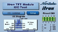
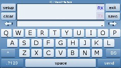
I2C Interface Test Project
|
|
This application allows you to test I2C Interface. You can change various options in the I2C setup. You can communicate between modules using the available keyboard and I2C interface.
|
|
Designer: ITRON Available for 4.3", 5.7", 7.0" : Download Zip File
|
|
|
|
|
|
|
|
Update Information |
Version |
Title |
Date |
Details |
49.58 |
I2C |
07 Sep 15 |
|
* Added repstart setup parameter to allow repeated start in master write / read
|
|
49.51 |
Problem when Port Encode Not Specified |
21 Jan 14 |
|
* A problem was found when the port encode was not being specified, the default should be Ascii Text but was being left undefined.
eg
SETUP( RS2 )
{
... settings ...
encode = s; // If no encode then an error can occur.
}
* This is now fixed.
|
|
49.44 |
Nesting of priority INT()s |
09 Oct 13 |
|
New functionality has been added to support nesting of priority INT()s, ie a priority interrupt can be interrupted by another priority interrupt with a higher priority (this is now the default behaviour).
A system setup variable has been added to disable this functionality.
SETUP(SYSTEM){ intNest = y | n; } // default = y;
For 'y', priority INT()s can be interrupted by higher priority INT()s
For 'n', priority INT()s run to completion, then the highest pending priority INT() is processed next.
|
|
49.44 |
Real Time (Priority) Interrupts |
09 Oct 13 |
|
This issue has been resolved. A problem was found with the operating systems' nested interrupt handler. New functionality has been implemented and tested.
Nesting of priority INT()s has also been added - see TFT Improvement
|
|
49.37 |
I2C IRQ hardware line |
10 Jun 13 |
|
* IRQ line now connected to CN3 pin 6 without need to connect solder link.
|
|
49.37 |
Serial Port Buffer Resizing |
10 Jun 13 |
|
* Added the ability to increase size of receive and transmit buffers.
> When a buffer size is increased then the old buffer is discarded (memory is not freed) and a new block of memory is allocated for the new buffer. Read and write pointers are reset and all data is flushed.
* Decreasing a buffer's size has no effect.
* The following ports are affected: RS2, RS4, AS1, AS2, DBG, USB, I2C, SPI
|
|
49.37 |
Losing Serial Interrupts with ''proc'' |
10 Jun 13 |
|
A new INT() processing scheme has been written which has abandoned a "counter" method and instead checks to see if there are any further "packets" waiting to be processed when the INT() command is run.
The old scheme made use of a counter which was incremented in the "hardware" interrupt handler when a packet was received and then decremented when a LOAD(buf,port); was performed from the INT() function. It had been found that the counter can get out of sync with the packets being received and hence packets are left in the receive buffer when the counter has a value of zero.
The new method, sets a task flag in the "hardware" interrupt handler to say a packet has been received. The INT() function then reads the packet when the LOAD(buf,port); command is used and then checks to see if there is another complete packet in the receive buffer. If there is, then the INT() function is called again, and so on, until there are no more complete packets and then the INT() is exited and normal processing resumes.
|
|
49.37 |
Serial Ports - use with d16l, d16m, d32l, d32m, h16l, h16m, h32l, h32m |
10 Jun 13 |
|
Corrected output for d16l, d16m, d32l, d32m, h16l, h16m, h32l, h32m when source is text variable.
|
|
49.19 |
I2C/SPI - Amended IRQ function to support multiple module connection. |
05 Oct 12 |
|
Amended IRQ function to support multiple module connection
Options:
N = No function
L = Enabled (always set to output, goes LOW when data is available to read, same as Y)
H = Enabled (always set to output, goes HIGH when data is available to read)
B = Buffered (set to input in idle state, output / LOW when data is available to read)
|
|
49.18 |
I2C - Amended IRQ function to support multiple module connection. |
22 Sep 12 |
|
Amended IRQ function to support multiple module connection
* New options:
N = No function Y = Enabled (always set to output, goes LOW when data is available to read) B = Buffered (set to input in idle state, output / LOW when data is available to read)
|
|
49.16 |
I2C - Added 'irq' parameter to setup. |
14 Sep 12 |
|
Added 'irq' parameter to setup. Options are Y/N. Default is N. When Y pin 6 of CN3 is configured as output and is normally high. It goes low when data is loaded into TX buffer and returns high when TX buffer is empty.
* Fixed bug in slave mode that results in 'end' value being sent as first byte of first read operation.
|
|
49.03 |
I2C - Added write to I2C reset bit in control register when configuring the interface. |
01 Jun 12 |
|
Added write to I2C reset bit in control register when configuring the interface.
This provides a way to clear any bus lockup using a timeout on no data received.
Configuration occurs anytime either a SETUP(I2C){...} is executed or any LOAD(I2C.param, value).
* Rewritten interrupt handlers as some combinations of event were not being handled correctly.
|
|
48.24 |
I2C - End character added to slave transmit on empty buffer. |
10 Mar 12 |
|
End character added to slave transmit on empty buffer.
|
|
47.24 |
I2C Address Modification |
31 Oct 11 |
|
Changed interrupt handling - some work still required!
* IMPORTANT! Changed address parameter so in all cases the address is specified as the true 7 bit value (not shifted left 1 bit as previously in some cases)
|
|
42.04 |
I2C slave and master - Master mode re-initiated from v42 to handle \\00 correctly. |
31 Mar 11 |
|
Master mode re-initiated from v42 to handle \\00 correctly.
|
|
39.00 |
I2C Master - I2C port now runs in raw data mode with Master mode. |
21 Jan 11 |
|
I2C port now runs in raw data mode with Master mode.
The user can control external I2C devices using the LOAD(I2C,,,sndbyte,...);
2nd parameter is the address of the I2C device
3rd parameter the number of bytes you require to be read back from the I2C device.
4th + parameters are the commands to be sent to the device prior to reading back
Example:
LOAD(I2C,20,3,47); //send command 47 to I2C device at address 20 and read back 3 bytes
LOAD(recvar,I2C); //put bytes into processing variable
.
Some devices require a delay before read back so 2 LOAD commands are issued
LOAD(I2C,35,0,16); //send command to I2C device at address 35
WAIT(40); //wait for processing if required
LOAD(I2C,35,4); //request 4 byte to be read from I2C device
LOAD(recvar,I2C); //load
|
|
32.00 |
TWI/I2C - Master mode added (further testing required). |
14 Oct 10 |
|
Master mode added (further testing required).
|
|
26.00 |
I2C - Addition of I2C slave mode when not a command port. |
06 Sep 10 |
|
Addition of I2C slave mode when not a command port
|
|
20.00 |
I2C - Added I2C interface |
22 Jul 10 |
|
Added I2C interface
|
|
|
|