|
|
CANBUS |
|
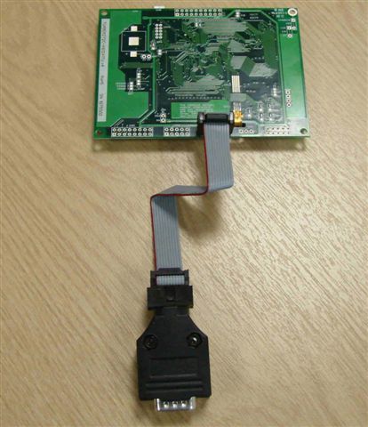
When attaching a CANBUS adaptor type EMCBK33 to CN3 using a 10 way IDC
cable, the connector is fitted to the backside of the module and the
following set up is required to match the default settings in the adaptor.
setup(AS1)
{
baud=38400;
//num = 110 to 115200. Any value can be set
to allow trimming for deviating clocks i.e. 38450
data=8;
//num = 5, 6, 7, 8
stop=1;
//num = 1, 15, 2 - note 15 is 1.5 bits
parity=N;
//first letter of Odd, Even, None,
Mark, Space
rxi=C;
//set receive buffer
interface as active (Y), a command processing source (C) or disable (N).
Default = N
encode=sr;
//set s=ASCII, w=UNICODE, m=UTF8 or use sr, wr
and mr specifying raw data bytes.
flow=H;
//none, hardware RTS/CTS
or DTR/DSR, software XON XOFF
}
The default receive address for the adaptor is ID=155h with 11bit or 29bitID
packets accepted (2.0a or 2.0b spec)
All bytes are received on AS1 with 1 to 8 bytes of data.
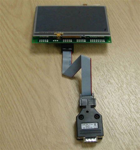
The transmit ID is also 155H. with data sent via AS1 with data length
of 1.Connection to an iSMART TFT is shown below.
Data Sheet

Operating modes
Communication with the EMCBK33A can be in binary or text format. The factory
default mode is binary (this is the only mode available in the v1 product).
When the operating mode is changed the mode is stored in EEPROM.
In binary mode every CAN data message received with the configured receive ID
is processed and the data bytes extracted from the packet and sent in raw
binary format to the target device. Each byte received from the target device
is sent on the CAN bus with the configured transmit ID as a single 1 byte
packet. Although an ID mask can be set to allow the reception of messages from
a range of CAN ID�s the CAN ID itself is not communicated to the target.
Text mode allows more flexibility and maintains all information about the CAN
packet when transferring to / from the target device. A disadvantage of text
mode is more bytes are transferred on the target side as messages are sent as
ASCII text (ASCII HEX for ID and data values). Depending on the CAN bitrate and
async baud rate this can lead to a limited throughput of data. Using receive ID
filtering with appropriate mask values can help by limiting the range of ID�s
accepted. Text mode is preferred when using the EMCBK33A with the iSMART TFT
modules because processing of the incoming data on the async port AS1 can be
triggered on <CR> and the preceding text packet analyzed using a series of CALC
commands to determine packet type, ID, length, payload data, etc. Transmission
is also more flexible as a CAN message can be sent with any ID on the fly using
the same, easy to read text format.
Binary mode
Configuration
Default settings are CAN ID = 155h, both 11 bit and 29 bit ID CAN messages
received, 11 bit CAN messages transmitted, CAN bit rate of 1Mbit/s,
asynchronous baud rate = 38400, SPI mode 0 (fixed 1Mhz clock speed). When a
configuration command is received the new configuration settings are stored in
EEPROM and the controller performs an internal reset and the new settings are
used immediately. Only a small selection of settings are available if
configured using the internal jumper links.
Changing the configuration via the CAN bus
Setup via the CAN bus is achieved by sending a single CAN message with ID=0h
(either 11 or 29 bit ID accepted). The data length of all CAN configuration
messages must be 8 bytes (unused parameter bytes at the end of the packet must
be sent but can be any value). The format of the 8 data bytes is as follows :-
Byte 1 Byte 2 Byte 3 Byte 4 Byte 5 Byte 6 Byte 7 Byte 8
�C� �f� type param1 param2 param3 param4 param5
If a message is received via CAN with an ID of 0h that does not match this
format no further messages with ID of 0h are processed until the controller is
powered OFF / ON.
Changing the configuration via the asynchronous interface
Setup via the asynchronous interface is achieved by sending a configuration
sequence at the currently selected baud rate. Unlike setting via the CAN bus
the packet length depends on the configuration type.
Byte 1 Byte 2 Byte 3 Byte 4 Byte 5 � Byte n
1Bh �C� �f� type param1 paramn
Configuration commands � [1Bh] is sent first when sending the
configuration via the asynchronous interface.
�A� Set Async baud rate
Set the asynchronous baud rate
[1Bh] 43h 66h 41h baud
Baud -
4800 00h
9600 01h
19200 02h
38400 03h
57600 04h
115200 05h
�B� Set CAN bit rate
Set the CAN bit rate from a range of common values. Different bit rates are
possible by using the custom option.
[1Bh] 43h 66h 42h rate
[1Bh] 43h 66h 42h rate [b1] [b2] [b3]
Rate -
20K 00h
50K 01h
100K 02h
125K 03h
200K 04h
250K 05h
500K 06h
1M 07h
Custom FFh (uses b1, b2 and b3 to create non-standard bit rate � contact us for
details)
�C� Set CAN receive / transmit modes and select either Async / SPI mode
Set either asynchronous or SPI mode. Set whether 11 bit or 29 bit ID will be
used for CAN transmit. Set the CAN receiver to accept 11 bit, 29 bit or both
formats.
[1Bh] 43h 66h 43h mode
Mode -
Bit 7 Bit 6 Bit 5 Bit 4 Bit 3 Bit 2 Bit 1 Bit 0
A/S - - - - CANTX CANRX2 CANRX1
A/S 0=Async, 1=SPI
CANTX 0=11 bit CAN transmit mode, 1=29 bit CAN transmit mode
CANRX 01=11 bit CAN receive mode, 10=29 bit CAN receive mode, 11=both 11 and 29
bit CAN receive mode
�Y� Enter text mode � controller is reset after this command
After this command is sent the controller operates in text mode.
�Z� Reset controller to factory defaults
�R� Set CAN receive ID (11 bit)
Specify the 11 bit ID to use for CAN receive.
[1Bh] 43h 66h 52h 00h [b1] [b2]
b1 11 bit ID (bits 10-8)
b2 11 bit ID (bits 7-0)
�R� Set CAN receive ID (29 bit)
Specify the 29 bit ID to use for CAN receive.
[1Bh] 43h 66h 52h 01h [b1] [b2] [b3] [b4]
b1 29 bit ID (bits 28-24)
b2 29 bit ID (bits 23-16)
b3 29 bit ID (bits 15-8)
b4 29 bit ID (bits 7-0)
�T� Set CAN transmit ID (11 bit)
Specify the 11 bit ID to use for CAN transmit.
[1Bh] 43h 66h 54h 00h [b1] [b2]
b1 11 bit ID (bits 10-8)
b2 11 bit ID (bits 7-0)
�T� Set CAN transmit ID (29 bit)
Specify the 29 bit ID to use for CAN transmit.
[1Bh] 43h 66h 54h 01h [b1] [b2] [b3] [b4]
b1 29 bit ID (bits 28-24)
b2 29 bit ID (bits 23-16)
b3 29 bit ID (bits 15-8)
b4 29 bit ID (bits 7-0)
�S� Set SPI mode
Sets SPI parameters. SPI is currently operational in transmit only (EMCBK33A ->
Module). Data order, polarity and phase can be set. Clock frequency is fixed at
1Mhz.
[1Bh] 43h 66h 53h mode
Mode
Bit 7 Bit 6 Bit 5 Bit 4 Bit 3 Bit 2 Bit 1 Bit 0
- - - - - DORD POL PHASE
DORD 0=MSB sent first, 1=LSB sent first
POL 0=clock idle low, 1=clock idle high
PHASE 0=leading edge clock, 1=trailing edge clock
Example setup
Text mode (v2 only)
Overview
In text mode all communication between the EMCBK33A v2 and the target device is
in the form of ASCII text packets.
Commands to controller
O<CR> Open the CAN channel (LED bright cyan) (stored in EEPROM, default =
closed)
CAN messages can be sent and received. The bitrate must be set up before the
CAN channel is opened.
C<CR> Close the CAN channel (LED dim cyan) (stored in EEPROM, default = closed)
No CAN messages can be sent or received.
Br<CR> Set standard CAN bit rate (stored in EEPROM, default = 1M)
r=0 20K
r=1 50K
r=2 100K
r=3 125K
r=4 200K
r=5 250K
r=6 500K
r=7 1M
This command should be sent while the CAN channel is closed.
bxxyyzz<CR> Sets custom CAN bit rate (stored in EEPROM)
Register 1 xx xddddddx d=divider
Register 2 yy xssxpppx ss=SJW, p=propogation
Register 3 zz xhhhHHHx h=phase2, H=phase1
Bitrate (bps) = 16000000 / [ (divider+1) x ( 1+ (p+1) + (h+1) + (H+1) ) ]
Example � 88.8Kbps
Divider (to derive TQ from master clock) = 8
xx x001000x
yy x10x111x
zz x100101x b104E4A<CR>
This command should be sent while the CAN channel is closed.
txxxl[data]<CR> Send a standard 11 bit data CAN message with ID of xxx, length
l and optional data
Only valid if CAN channel is open.
Example t100410203040<CR> sends an 11 bit packet with ID of 100h and 4 data
bytes 10h, 20h, 30h, 40h
Txxxxxxxxl[data]<CR> Send an extended 29 bit data CAN message with ID of
xxxxxxxx, length l and optional data
Only valid if CAN channel is open.
Example T000012FE1F5<CR> sends a 29 bit packet with ID of 000012FEh and 1 data
bytes F5h
rxxxl<CR> Send a standard 11 bit remote CAN message with ID of xxx and length l
Only valid if CAN channel is open.
Example r7FE3<CR> sends an 11 bit RTR packet with ID of 7FEh with length of 3
Rxxxxxxxxl<CR> Send an extended 29 bit remote CAN message with ID of xxxxxxxx
and length l
Only valid if CAN channel is open.
Example r100000FE2<CR> sends a 29 bit RTR packet with ID of 100000FEh with
length of 2
ixxx<CR> Set standard 11 bit receive ID (stored in EEPROM, default = 000)
Example i7FF<CR> sets 11 bit receive ID to 7FFh (see corresponding mask command
for message filtering)
mxxx<CR> Set standard 11 bit receive MASK (stored in EEPROM, default = 000).
Use in conjunction with receive ID to set up
receive filtering.
Ixxxxxxxx<CR> Set extended 29 bit receive ID (stored in EEPROM, default =
00000000)
Mxxxxxxxx<CR> Set extended 29 bit receive MASK (stored in EEPROM, default =
00000000)
Xn<CR> Enable / disable timestamp info on RX packets (0=disable, 1=enable)
(stored in EEPROM, default = disabled)
Un<CR> Sets async baud rate (stored in EEPROM, default = 38400)
0=4800
1=9600
2=19200
3=38400
4=57600
5=115200
Q<CR> Return version information and current configuration
F<CR> Return CAN status flags in the form Fxx<CR>
bit 7 -
bit 6 timestamp enabled
bit 5 CAN enabled
bit 4 CAN initiated
bit 3 -
bit 2 -
bit 1 bus off error
bit 0 passive error
Y<CR> Enter binary mode � controller is reset after this command
Z<CR> Reset controller to factory defaults
Lrrggbb<CR> LED test - sets colour to RGB HEX values
Format of commands received
dxxxl[data][tttt]<CR> Standard data CAN message received with ID, length,
optional data and timestamp data if enabled
Dxxxxxxxxl[data][tttt]<CR> Extended data CAN message received with ID, length,
optional data and timestamp data if enabled
rxxxl[tttt]<CR> Standard remote CAN message received with ID, length and
timestamp data if enabled
Rxxxxxxxxl[tttt]<CR> Extended remote CAN message received with ID, length and
timestamp data if enabled
Example setup
For use in an 250Kbps 11 bit system. Filter so only packets with ID�s between
170h and 17Fh are received. Enable receive timestamp.
B5<CR> Set bitrate
i170<CR> Set ID
m7F0<CR> Set mask
X1<CR> Enable timestamp
O<CR> Open CAN channel
|
|
Update Information |
Version |
Title |
Date |
Details |
36.00 |
Serial Send/Receive |
23 Nov 10 |
|
The data encode parameter for serial ports now shows sr, wr, mr on the web for raw data bytes (00h-FFh,0000h-FFFFh) CANBUS setup shown on the website when used with EMCBK33A adaptor and AS1
|
|
|
|